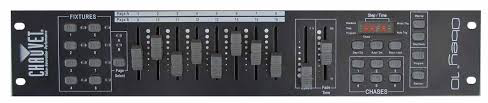
Chauvet Obey 10
|
 |
| ARCHITECTURE |
|---|
| The Chauvet Obey 10 (OB-10) rack mount controller is a fairly versatile unit capable of controlling 128 DMX channels allocated into 8 fixtures of 16 channels each which is ideal for basic control of many intelligent fixtures including lasers, moonflowers, sweepers, mushrooms, and scanners among others. Channels can be reassigned within fixture groups, fader direction can be reversed on any channel, and fade mode can be set on any channel. Six chases consisting of up to 999 steps can be programmed. Chases can be played manually using up and down buttons as a scene mode. Chase fade time and speed can be controlled during automatic chase playback. Chases can be played by sound triggering. Chases can be run individually or stacked. Individual fixtures can be operated over top of chases. In addition to preset chases, individual fixtures can be operated manually, either individually or in a group allowing some to be used for area lighting while others are performing sequenced chases. |
Modes: The nine main modes include:
|
|
Caveats: •There is a limitation of 6 chases of 999 steps, however chases can be cascaded. •Because the OB-10 is designed for intelligent lights, it does not have features like masters, submasters, or bump buttons needed for conventional lighting. Consider the Stage Designer 50 for that role. •While it is possible to operate moving lights with this controller, it is less than ideal for that purpose. Consider the Obey 70 for that role. •There is no capability to view outputs expressed as percentages. •There are no strobe or fogger controls in this device. Consider Obey 40 or 70 for these. •There is no MIDI capability in this device. Consider Obey 40 or 70 or Stage Designer 50 if you need it. |
|
DMX Channel Assignments: Fixture/Channels:
|
|
Setup Strategy: The following steps outline the general procedure to follow in setting up and using the OB-10 for either designed shows or for busking. Step One: Perform either a "SYSTEM RESET" as needed to clear out existing settings. Step Two: Use "CHANNEL" reassignment to conform all fixtures to a standard convention if needed. Step Three: Use fader "REVERSE" to conform pan/tilt controllers to a standard convention if needed. Step Four: Use fader "FADER DISABLE" to switch the channel between fade and switch mode if needed. Step Five: "PROGRAM" all chases as needed. Step Six: Run the show using "MANAUL", "AUTO", and "MUSIC" modes. |
|
Power Supply: 12 Volts DC, 500 milliAmperes, 5.5 X 2.1 mm plug |
| The Obey 10 controller features a great deal of functionality condensed into a modest number of multifunction controls which do different things depending on the current mode. These control functions can be divided into groups by function: Mode Selection, Configuration, and Execution. Generally speaking, mode controls maintain their current status until explicitly changed. Execution controls work while in "MANUAL", "AUTO", or "MUSIC" mode, and Configuration controls operate within specific mode context. |
MODE SELECTION
| CHANNEL PATCH MODE | |
|---|---|
|
To Enter: Press [PROGRAM] & [STEP] together once. The 'step' indicator turns on. |
To Exit: Press [PROGRAM] & [STEP] together twice. The 'step' indicator turns off. |
|
The "CHANNEL PATCH" mode allows DMX channels to be reassigned with respect to faders.
Faders can be assigned to channels or channels assigned to faders so that its
possible to assign all sixteen DMX channels of a fixture to just one fader or all
sixteen faders to one DMX channel. It's also possible that after reassignment,
some faders may not have any channels assigned to them or vice versa. Multiple fixtures can be patched simultaneosly. | |
| FADER REVERSAL MODE | |
|---|---|
|
To Enter: Press [PROGRAM] & [STEP] together twice. The 'step' indicator turns on and the display shows a "r" in the first position. |
To Exit: Press [PROGRAM] & [STEP] together twice. The 'step' indicator turns off and display no longer shows "r" in the first position. |
|
This mode allows the direction faders move to be reversed so, for example, moving a fader up causes the
fixture to move upward instead of downward. | |
| FADER MODE | |
|---|---|
|
To Enter: Press [BLACKOUT] & [STEP] together once. The 'step' indicator turns on and the display shows a "F" in the first position. |
To Exit: Press [BLACKOUT] & [STEP] together once. The 'step' indicator turns off and the display no longer shows an "F" in the first position. |
|
Certain features of moving lights expect a switched (on - off) control signal rather than a variable 0-255 dmx
value. Individual faders can be changed from variable to binary output. | |
| PROGRAM MODE | |
|---|---|
|
To Enter: Press and hold PROGRAM [Program] for three seconds. LCD Display "Program"" indicator starts flashing. |
To Exit: Press and hold PROGRAM [Program] for three seconds. LCD Display "Program" indicator turns off. |
| "PROGRAM" mode allows the creation and deletion of steps and chases. The left most digit in the display indicates the current chase, the right three digits indicate the current step within that chase. Chase "0" is independent mode where fixtures can be operated manually while remaining in auto or music mode. This allows some fixtures to be used for area lighting and the others for chases. | |
| MANUAL MODE | |
|---|---|
|
To Enter: If LCD Display indicates "Music Trg", press MUSIC [Music/Add] button. If LCD Display indicates "Auto Trg", press AUTO [Auto/Del] button. If LCD Display indicates "Program", press and hold PROGRAM [Program] button for three seconds. LCD Display will have no indicators lit. |
To Exit: Press and hold PROGRAM [Program] for three seconds, or press AUTO [Auto/Del], or MUSIC [Music/Add]. |
|
When in manual mode, fixtures can be selected by pressing one or more FIXTURE buttons and
controlled by fader action. | |
| AUTO MODE | |
|---|---|
|
To Enter: Press AUTO [Auto/Del] button. LCD Display "Auto Trg" indicator lights up. |
To Exit: Press AUTO [Auto/Del] button to return to manual mode. or MUSIC [Music/Add] to enter music mode. or press and hold PROGRAM [Program] to enter program mode. |
|
"Auto" allows chases to run controlled by SPEED [Speed] and FADE TIME [Fade Time] sliders. | |
| MUSIC MODE | |
|---|---|
|
To Enter: Press MUSIC [Music/Add] button LCD Display "Music Trg" indicator lights up |
To Exit: Press MUSIC [Music/Add] button to return to manual mode, or AUTO [Auto/Del] button to return to automatic mode, or press and hold PROGRAM [Program] button to enter program model. |
|
Music mode synchronizes the chase speed to the music beat. | |
| BLACKOUT MODE | |
|---|---|
|
To Enter: Press BLACKOUT [Blackout] button. The 'Blackout' indicator begins flashing. |
To Exit: Press BLACKOUT [Blackout] button. The 'Blackout' indicator turns off. |
|
This mode disables any output from the controller allowing blind programming or the ability to take the
stage to black during the performance. | |
CONFIGURATION
| SYSTEM RESET | |
|---|---|
|
To Execute: Press down STEP UP [Step Up] and DELETE [Auto/Del] buttons Indicators will flash showing The reset operation has occurred. | |
|
System Reset returns the device to factory defaults. The primary purpose is to reset
channel assignments, fader reverses, fade disable, and chase programs. It works in any mode. | |
|
CHANNEL PATCHING Reassigning Faders 1—16 for a fixture |
|---|
Fader/Channel reassignment can be done three ways:
|
|
To assign channels to faders (preferred) Check "Step" is active. LCD Display Step indicator is lit. Select one or more [FIXTURE 1—8].Note: Some faders may not have channels associated with them (orphaned faders). When all reassignments are complete, exit the mode. |
|
To assign faders to channels (non preferred) Check "Step" is active. LCD Display Step indicator is lit. Select one or more [FIXTURE 1—8].Note: Some channels may not have faders associated with them (orphaned channels). Channels with multiple faders assigned will function as "pile on" or highest takes precendence (HTP). When all reassignments are complete, exit the mode. |
| To facilitate programming and manual operation, it is useful to conform fixture functions so that the various functions are mapped to the same faders by some convention. See table below for a possible convention chart. It is far more intuitive to assign channels to faders than faders to channels and mixing the methods is chaotic at best and should be avoided. Since channel patching is relative within a fixture, you don't need to be concerned with actual DMX offsets. |
|
CHANNEL PATCHING Copying fixture reassignments |
|---|
|
It is unnecessary to manually enter reassignments for identical fixtures and deal with orphaned channels. To
copy assignments from one fixture to another: Check "Step" is active. LCD Display Step indicator is lit. Press and hold [FIXTURE 1—8] button being copied from.When all copies are complete, exit the mode. |
| Fixture copying does not copy Fader Reverses because they have more to do with fixture placement and orientation, that is, identical fixture types may have different reversal patterns. |
|
CHANNEL PATCHING Viewing channel reassignments for a fixture |
|---|
|
Check "Step" is active. LCD Display Step indicator is lit. Select [FIXTURE 1—8].When finished viewing channel assignments, exit the mode. |
|
FADER REVERSAL Reverse fader/controller direction |
|---|
|
Check "Step" is active. LCD Display Step indicator is lit and 'r' is displayed in first position. Select one or more fixtures [FIXTURE 1—8].When finished reversing faders, exit the mode. |
| Generally, fader/controller reversal is only needed for the axis controllers but any fader can be reversed. This is a powerful feature that allows fixtures to move by convention: up moves fixtures up, left, or upstage, down moves fixtures down, right or downstage. See chart below as an example. |
|
FADER REVERSAL Viewing fader reversals for a fixture |
|---|
|
Check "Step" is active. LCD Display Step indicator is lit and 'r' is displayed in first position. Select [FIXTURE 1—8].When finished viewing fader reversals, exit the mode. |
|
FADER TYPE Set fader mode |
|---|
|
Check "Step" is active. LCD Display Step indicator is lit and 'F' is displayed in first position. Select one or more fixtures [FIXTURE 1—8].When finished changing modes, exit the mode. |
| Generally, fader mode switching is only needed for the gobo controllers but any fader can be changed. In switched mode, dmx output is either zero or 255 and is appropriate for fixture channels that need binary on and off control. |
|
FADER TYPE Viewing fader types for a fixture |
|---|
|
Check "Step" is active. LCD Display Step indicator is lit and 'F' is displayed in first position. Select [FIXTURE 1—8].When finished viewing fader mode assignments, exit the mode. |
|
PROGRAM MODE Clear a chase |
|---|
|
Check "PROGRAM" Mode is active. LCD Display "Program" indicator is flashing. Press DELETE [Auto/Del] and desired CHASE [Chase 1—6] simultaneously.When finished clearing chases, exit the mode. |
|
PROGRAM MODE Insert a new step onto a chase |
|---|
|
Check "PROGRAM" Mode is active. LCD Display "Program" indicator is flashing. Set BLACKOUT [Blackout] off Blackout indicator is not lit.When finished inserting steps, exit the mode. |
| Note: When moving from Page A to B or Page B to A, you must move each fader slightly to get the controller to recognize the new setting. |
|
PROGRAM MODE Remove a step from a chase |
|---|
|
Check "PROGRAM" Mode is active. LCD Display "Program" indicator is flashing. Set BLACKOUT [Blackout] off Blackout indicator is not lit.When finished removing steps, exit the mode. |
|
PROGRAM MODE View steps in a chase |
|---|
|
Check "PROGRAM" Mode is active. LCD Display "Program" indicator is flashing. Set BLACKOUT [Blackout] off Blackout indicator is not lit.When finished viewing steps, exit the mode. |
|
PROGRAM MODE Edit a step in a chase |
|---|
|
Check "PROGRAM" Mode is active. LCD Display "Program" indicator is flashing. Set BLACKOUT [Blackout] off Blackout indicator is not lit.When finished editing steps, exit the mode. |
EXECUTION
|
MANUAL MODE Control a fixture |
|---|
|
Check "MANUAL" Mode is active. LCD Display "Program", "Auto Trg", and "Music Trg" should not be lit. Set BLACKOUT [Blackout] off Blackout indicator is not lit. |
|
AUTO MODE Play a chase |
|---|
|
Check "AUTO" Mode is active. LCD Display "Auto Trg" indicator should be lit. Set BLACKOUT [Blackout] off Blackout indicator is not lit.Note 1: selected chases play in sequential order and can be toggled on and off as needed. Note 2: chases can be overridden by manual operation of fixtures and faders (HTP). Note 3: chases can be blacked out but will continue to run. |
|
MUSIC MODE Play a chase to music beat |
|---|
|
Check "MUSIC" Mode is active. LCD Display "Auto Trg" indicator should be lit. Set BLACKOUT [Blackout] off Blackout indicator is not lit.Note 1: selected chases play in sequential order and can be toggled on and off as needed. Note 2: chases can be overridden by manual operation of fixtures and faders (HTP). Note 3: audio is picked up by a microphone sensor in the controller and there is no level control. Note 4: chases can be blacked out but will continue to run. |
SAMPLE FADER CONVENTIONS
FOR INTELLEGENT FIXTURES
| FADER CONVENTIONS | |||
|---|---|---|---|
| Page A Faders | Description | Page B Faders | Description |
| 1 | 9 | ||
| 2 | 10 | ||
| 3 | 11 | ||
| 4 | 12 | ||
| 5 | 13 | ||
| 6 | 14 | ||
| 7 | 15 | ||
| 8 | 16 | ||
SAMPLE FADER REVERSE CONVENTIONS
FOR INTELLIGENT FIXTURES
| FADER REVERSAL CONVENTIONS | |||
|---|---|---|---|
| Fixture Height | Facing Direction | Pan | Tilt |
| High (truss mounted) | Upstage | NORMAL | REVERSE |
| Downstage | REVERSE | REVERSE | |
| Stage Left | NORMAL | REVERSE | |
| Stage Right | REVERSE | REVERSE | |
| Low (Floor mounted) | Upstage | REVERSE | NORMAL |
| Downstage | NORMAL | NORMAL | |
| Stage Left | REVERSE | NORMAL | |
| Stage Right | NORMAL | NORMAL | |
| DISCLAIMER |
|---|
| This training manual was developed by Stagecraft Production Service independently from Chauvet for staff and client training purposes. No warranty express or implied exists with respect to the accuracy of information contained within and users are advised to use the information contained within at their own risk. Users should consult the official documentation for this product for information that may not be present herein. It should not be considered as a replacement or substitute for the official documentation. |