Chauvet Obey 70
|
 |
| ARCHITECTURE |
|---|
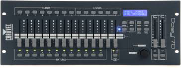
| The Chauvet Obey 70 (OB-70) rack mount controller is a fairly versatile unit capable of controlling 384 DMX channels allocated into 12 fixtures of 32 channels each which is ideal for high end moving lights. It provides programming of up to 240 scenes divided into 30 banks of eight. Each Scene Bank can be played back as a chase of up to 8 steps giving the possibility of up to thirty short chases. Additionally, six long chases consisting of up to 240 steps can be programmed consisting of any combination of scenes in any order. Two additional control channels are provided for Chauvet compatable strobes and hazers/foggers. In addition to preset scenes and chases, individual fixtures can be operated manually. 120 scenes and 6 chases can be triggered via MIDI channels 1-16. |
|
Strobe Controller: consists of a button, an indicator, and a 1/4" phone jack on the rear panel. When pressed, the button outputs +10VDC pulses to the tip of the phone jack. The indicator flashes at the same rate. This is the industry standard for remote controlling non DMX strobes. |
|
Fogger/Hazer Controller: consists of a button, an indicator, and 5 pin DIN style connector on the real panel. The indicator glows when the device is up to temperature and the button emits fog/haze. Pin 1 is the anode of the LED device, pin 2 is the button, and pin 4 is the common. Pin 5 is not used, and the fogger/hazer devices provide +5VDC on pin 3 to power remote controllers (the OB-70 doesn't need this.) |
|
Modes: The nine main modes include:
|
|
Caveats: •There is a limitation of 240 scenes and 6 chases. •Only the Scene Banks 1—15 are accessible via MIDI. •In manual mode, only one scene can be active at a time. •Because the OB-70 is designed for moving lights, it does not have features like masters, submasters, or bump buttons needed for conventional lighting. •Joysticks are assigned to faders 15 (tilt) & 16 (pan) on Page A and 31 (tilt) & 32 (pan) on Page B by default. Since these are your X Axis and Y Axis yoke controllers, they need to be reassigned for each fixture. •The remote strobe control only outputs at a fixed rate and only works with non DMX controlled strobes. •The indicator lamp for the remote hazer/fogger controller is a LED and operates at around +4VDC and the switch is intended for logic level low voltage and low current and is fully compatible with all Chauvet hazers/foggers with a five pin DIN remote jack. Older foggers/hazers have 110 VAC neon lamps and relay control circuits (typically using an IEC connector for the remote jack) and are *NOT* compatible without some type of converter between the two. The cost of such a device makes it unfeasible to adapt. Use a DMX controlled hazer/fogger instead. |
|
DMX Channel Assignments: Fixture/Channels:
|
|
Setup Strategy: The following steps outline the general procedure to follow in setting up and using the OB-70 for either designed shows or for busking. Step One: Perform either a "SYSTEM RESET", "DELETE ALL SCENES", or "DELETE ALL CHASES" as needed to clear out existing settings. Step Two: Use "CHANNEL" reassignment to conform all fixtures to a standard convention if needed. Step Three: Use fader "REVERSE" to conform pan/tilt controllers to a standard convention if needed. Step Four: "PROGRAM" all static scenes into low banks, short chase scenes into mid banks, and long chase scenes into high banks. Step Five: "PROGRAM" all long chasees needed. Step Six: Optionally, set "MIDI" channel if needed. Step Seven: Run the show using "MANAUL", "AUTO", and "MUSIC" modes and optionally, MIDI input. |
|
Power Supply: 9-12 Volts DC, 500 milliAmperes, 5.5 X 2.1 mm plug |
| The Obey 70 controller features a great deal of functionality condensed into a modest number of multifunction controls which do different things depending on the current mode. These control functions can be divided into groups by function: Mode Selection, Configuration, and Execution. Generally speaking, mode controls maintain their current status until explicitly changed. Execution controls work while in "MANUAL", "AUTO", or "MUSIC" mode, and Configuration controls operate within specific mode context. |
MODE SELECTION
| CHANNEL MODE | |
|---|---|
|
To Enter: Press [PROGRAM] & [DISPLAY] |
To Exit: Press [PROGRAM] & [DISPLAY][DISPLAY] |
| The "CHANNEL" mode allows DMX channels to be reassigned with respect to faders. Note that faders are fixed, its the DMX channel assignments that change. Its possible to assign all thirty two DMX channels of a fixture to just one fader. It's also possible that after reassignment, some faders may not have any channels assigned to them. | |
| REVERSE MODE | |
|---|---|
|
To Enter: Press [PROGRAM] & [DISPLAY][DISPLAY] |
To Exit: Press [PROGRAM] & [DISPLAY] |
|
This mode allows the direction faders move to be reversed so, for example, moving a fader up causes the
fixture to move upward. | |
| PROGRAM MODE | |
|---|---|
|
To Enter: [PROGRAM] (press and hold for three seconds). LCD Display indicates "PROGRAM". |
To Exit: [PROGRAM] (press and hold for three seconds). LCD Display indicates "MANUAL". |
| "PROGRAM" mode allows the creation, and deletion of scenes, and the creation and deletion of chases. | |
| MANUAL MODE | |
|---|---|
|
To Enter: If LCD Display indicates "MIDI", press [MIDI] button. If LCD Display indicates "MUSIC", press [MUSIC] button. If LCD Display indicates "AUTO", press [AUTO] button. If LCD Display indicates "PROGRAM", press and hold [PROGRAM] button for three seconds. LCD Display will indicate "MANUAL" |
To Exit: Simply enter "PROGRAM", "AUTO", "MUSIC", or "MIDI" mode. |
|
When in manual mode, fixtures can be selected and controlled by fader action, scenes can be switched on and off
one at a time. Note that [SPEED] and [FADE TIME] sliders do not affect behavior. When scenes are activated,
they "pile on" (HTP) to fader settings. | |
| AUTO MODE | |
|---|---|
|
To Enter: Press [AUTO] button. LCD Display reads "AUTO" |
To Exit: Press [AUTO] button to return to manual mode. or [MUSIC] to enter music mode. or [PROGRAM] to enter program mode. |
|
"Auto" allows chases to run controlled by [SPEED] and [FADE] sliders. | |
| MUSIC MODE | |
|---|---|
|
To Enter: Press [MUSIC] button LCD Display reads "MUSIC" |
To Exit: Press [MUSIC] button to return to manual mode, or [AUTO] button to return to automatic mode, or [PROGRAM] button to enter program model. |
|
Music mode synchronizes the chase speed to the music beat. | |
| MIDI MODE | |
|---|---|
|
To Enter: Press [MIDI] |
To Exit: Press [MIDI] |
|
This mode allows the selection of MIDI channels from 1—16. | |
| DELETE ALL SCENES MODE | |
|---|---|
|
To Execute: Toggle the power switch to the "OFF" position. Hold down [BANK DOWN] and [PROGRAM] buttons. Toggle the power switch to the "ON" position. All lights flash indicating success. | |
|
"Delete All Scenes" clears all scenes leaving other programming intact. | |
| DELETE ALL CHASES MODE | |
|---|---|
|
To Execute: Press and hold [PROGRAM] button for three seconds. Hold down [BANK DOWN] and [DEL] buttons. Toggle the power switch to the "OFF" position. | |
|
"Delete All Chases" clears all chasees leaving other programming intact. | |
| SYSTEM RESET MODE | |
|---|---|
|
To Execute: Toggle the power switch to the "OFF" position. Hold down [BANK UP] and [DEL] buttons Toggle the power switch to the "ON" position The reset operation can take up to 30 seconds to complete. | |
|
System Reset returns the device to factory defaults. The primary purpose is to reset
channel assignments and fader reverses. In most cases, deleting scenes and chases may
be sufficient if the fixtures haven't changed. | |
CONFIGURATION
|
CHANNEL MODE Reassigning Faders 1—14 & 17—30 for a fixture |
|---|
Fader/Channel reassignment can be done three ways:
|
|
Assign channels to faders (preferred) Check "CHANNEL" is active. LCD Display should show "CHANNEL" Select one or more [FIXTURE 1—12].Note: Some faders may not have channels associated with them (orphaned faders). When all reassignments are complete, exit the mode. |
|
Assign faders to channels (non preferred) Check "CHANNEL" is active. LCD Display should show "CHANNEL" Select one or more [FIXTURE 1—12].Note: Some channels may not have faders associated with them (orphaned channels). Channels with multiple faders assigned will function as "pile on" (HTP). When all reassignments are complete, exit the mode. |
| To facilitate programming and manual operation, it is useful to conform fixture functions so that the various functions are mapped to the same faders by some convention. See table below for a possible convention chart. It is far more intuitive to assign channels to faders than faders to channels and mixing the methods is chaotic at best and should be avoided. |
|
CHANNEL MODE Reassigning Joystock controls 15—16 & 31—32 for a fixture |
|---|
|
Check "CHANNEL" Mode is active. LCD Display should show "CHANNEL" Select one or more [FIXTURE 1—12]. When all reassignments are complete, exit the mode. |
|
CHANNEL MODE Copying fixture reassignments |
|---|
|
It is unnecessary to manually enter reassignments for identical fixtures and deal with orphaned channels. To
copy assignments from one fixture to another: Check "CHANNEL" Mode is active. LCD Display should show "CHANNEL" Press and hold [FIXTURE 1—12] button being copied from.When all copies are complete, exit the mode. |
| Fixture copying does not copy Fader Reverses because they have more to do with fixture placement and orientation, that is, identical fixture types may have different reversal patterns. |
|
CHANNEL MODE Viewing channel reassignments for a fixture |
|---|
|
Check "CHANNEL" Mode is active. LCD Display should show "CHANNEL" Select [FIXTURE 1—12].When finished viewing channel assignments, exit the mode. |
|
REVERSE MODE Reverse fader/controller direction |
|---|
|
Check "REVERSE" Mode is active. LCD Display should show "REVERSE" Select [FIXTURE 1—12].When finished reversing faders, exit the mode. |
| Generally, fader/controller reversal is only needed for the axis controllers but any fader can be reversed. This is a powerful feature that allows fixtures to move by convention: up moves fixtures up, left moves fixtures toward stage right or downstage. See chart below as an example. |
|
MIDI MODE Set the MIDI channel |
|---|
|
Check "MIDI" Mode is active. LCD Display should show "MIDI" Press [BANK UP] or [BANK DOWN] to select channelWhen finished setting MIDI channel, exit the mode. |
|
PROGRAM MODE Create or modify a scene |
|---|
|
Check "PROGRAM" Mode is active. LCD Display should show "PROGRAM" Select one or more [FIXTURES 1—12].When finished setting scenes, exit the mode. |
|
Note: Use low numbered banks for static scenes, the high numbered
banks for scenes used to build long chases, and the middle banks for short
chases to simplify execution. Note: To modify a scene, simply build the modified scene as above and store it to the Bank/Scene to be modified. The new scene will replace the existing one. |
|
PROGRAM MODE Deleting a single scene |
|---|
|
Check "PROGRAM" Mode is active. LCD Display should show "PROGRAM" Press [BANK UP] or [BANK DOWN] to select desired bank.When finished deleting scenes, exit the mode. |
|
PROGRAM MODE Deleting all scenes in a bank |
|---|
|
Check "PROGRAM" Mode is active. LCD Display should show "PROGRAM" Press [BANK UP] or [BANK DOWN] to select desired bank.When finished deleting scenes, exit the mode. |
|
PROGRAM MODE Record a scene to the end of a chase |
|---|
|
Check "PROGRAM" Mode is active. LCD Display should show "PROGRAM" Select [CHASE 1—6]Note: a chase is a set of pointers to scenes. If the underlying scene changes, it will change in the chase too. When finished setting chases, exit the mode. |
|
PROGRAM MODE Record a bank of scenes to the end of a chase |
|---|
|
Check "PROGRAM" Mode is active. LCD Display should show "PROGRAM" Select [CHASE 1—6]When finished copying banks, exit the mode. |
|
PROGRAM MODE Insert a new step into a chase |
|---|
|
Check "PROGRAM" Mode is active. LCD Display should show "PROGRAM" Set [BLACKOUT] on blue light glows.When finished inserting steps, exit the mode. |
|
PROGRAM MODE Deleting a step from a chase |
|---|
|
Check "PROGRAM" Mode is active. LCD Display should show "PROGRAM" Set [BLACKOUT] on blue light glows.When finished removing steps, exit the mode. |
|
PROGRAM MODE Delete a chase |
|---|
|
Check "PROGRAM" Mode is active. LCD Display should show "PROGRAM" Select [CHASE 1—6].When finished deleting chases, exit the mode. |
|
PROGRAM MODE Step through a chase |
|---|
|
Check "PROGRAM" Mode is active. LCD Display should show "PROGRAM" Set [BLACKOUT] on blue light glows. |
EXECUTION
|
MANUAL MODE Control a fixture |
|---|
|
Check "MANUAL" Mode is active. LCD Display should show "MANUAL" Select one or more [FIXTURES 1—12] |
|
MANUAL MODE Playback a scene or scenes in a bank |
|---|
|
Check "MANUAL" Mode is active. LCD Display should show "MANUAL". Set [BLACKOUT] on blue light glows.Note: the use of the Blackout button is to prevent unintended action and motion. Note: only one scene can playback at a time. |
|
AUTO MODE Play a short chase |
|---|
|
Check "AUTO" Mode is active. LCD Display should show "AUTO" Set [BLACKOUT] on blue light glows.Note: only programmed scenes will play, empty scenes skipped. Note: scenes play in sequential order. |
|
AUTO MODE Play a long chase |
|---|
|
Check "AUTO" Mode is active. LCD Display should show "AUTO" Set [BLACKOUT] on blue light glows.Note: selected chases play in sequential order . |
|
MUSIC MODE Play a short chase to music beat |
|---|
|
Check "MUSIC" Mode is active. LCD Display should show "MUSIC" Set [BLACKOUT] on blue light glows.Note: only programmed scenes will play, empty scenes skipped. Note: scenes play in sequential order. |
|
MUSIC MODE Play a long chase to music beat |
|---|
|
Check "MUSIC" Mode is active. LCD Display should show "MUSIC" Set [BLACKOUT] on blue light glows.Note: selected chases play in sequential order. |
SAMPLE FADER CONVENTIONS
FOR MOVING FIXTURES
| FADER CONVENTIONS | |||
|---|---|---|---|
| Page A Faders | Description | Page B Faders | Description |
| 1 | Coarse Dimmer | 17 | Fine Dimmer |
| 2 | Strobe | 18 | |
| 3 | Coarse Color Wheel | 19 | Fine Color Wheel |
| 4 | Static Gobo Wheel | 20 | |
| 5 | Coarse Rotating Gobo Wheel | 21 | Fine Rotating Gobo Wheel |
| 6 | Effect Speed | 22 | |
| 7 | Prism | 23 | |
| 8 | Fixture Mode | 24 | |
| 9 | 25 | ||
| 10 | 26 | ||
| 11 | Frost | 27 | |
| 12 | Coarse Focus | 28 | Fine Focus |
| 13 | Coarse Zoom | 29 | Fine Zoom |
| 14 | Motion Speed | 30 | |
| 15 | Course X-Axis (pan) | 31 | Fine X-Axis (pan) |
| 16 | Coarse Y-Axis (tilt) | 32 | Fine Y-Axis (tilt) |
SAMPLE FADER REVERSE CONVENTIONS
FOR MOVING FIXTURES
| FADER REVERSAL CONVENTIONS | |||
|---|---|---|---|
| Fixture Height | Facing Direction | Pan | Tilt |
| High (truss mounted) | Upstage | NORMAL | REVERSE |
| Downstage | REVERSE | REVERSE | |
| Stage Left | NORMAL | REVERSE | |
| Stage Right | REVERSE | REVERSE | |
| Low (Floor mounted) | Upstage | REVERSE | NORMAL |
| Downstage | NORMAL | NORMAL | |
| Stage Left | REVERSE | NORMAL | |
| Stage Right | NORMAL | NORMAL | |
MIDI TO DMX
| ABOUT MIDI |
|---|
| Musical Instrument Digital Interface (MIDI) was originally created in the 1980s to link
electronic musical instruments. Chauvet adapted MIDI for lighting control and it's a
feature in their controllers. MIDI consists of sixteen "channels" using hexadecimal coding
0 through F, however, Chauvet maps those to decimal 1 through 16 consistent with how it's
commonly deployed in musical instruments. There are two modes provided to allow the user
to select both MIDI in and MIDI output channels which allows consoles to be networked on
a MIDI network. It's possible for a PC running MIDI to communicate on all 16 channels,
though Obey 70s are better thought of as terminal nodes. Next, each MIDI channel has 128 possible "Notes" numbered from 0 through 127. The Obey 70 uses 127 notes, numbered from 0 through 126 where 'Middle C' is at Note 60. Each channel can emit or respond to a 'Note On' or 'Note Off' command. The following table maps out the respective command actions to their associated MIDI notes. |
|
MIDI MAPPING 127 Notes | |||
|---|---|---|---|
| Octave | Note | MIDI Note | OB-70 Command Actions |
| -1 | C | 0 | Bank 1, scene 1 is active. |
| C# | 1 | Bank 1, scene 2 is active. | |
| D | 2 | Bank 1, scene 3 is active. | |
| D# | 3 | Bank 1, scene 4 is active. | |
| E | 4 | Bank 1, scene 5 is active. | |
| F | 5 | Bank 1, scene 6 is active. | |
| F# | 6 | Bank 1, scene 7 is active. | |
| G | 7 | Bank 1, scene 8 is active. | |
| G# | 8 | Bank 2, scene 1 is active. | |
| A | 9 | Bank 2, scene 2 is active. | |
| A# | 10 | Bank 2, scene 3 is active. | |
| B | 11 | Bank 2, scene 4 is active. | |
| 0 | C | 12 | Bank 2, scene 5 is active. |
| C# | 13 | Bank 2, scene 6 is active. | |
| D | 14 | Bank 2, scene 7 is active. | |
| D# | 15 | Bank 2, scene 8 is active. | |
| E | 16 | Bank 3, scene 1 is active. | |
| F | 17 | Bank 3, scene 2 is active. | |
| F# | 18 | Bank 3, scene 3 is active. | |
| G | 19 | Bank 3, scene 4 is active. | |
| G# | 20 | Bank 3, scene 5 is active. | |
| A | 21 | Bank 3, scene 6 is active. | |
| A# | 22 | Bank 3, scene 7 is active. | |
| B | 23 | Bank 3, scene 8 is active. | |
| 1 | C | 24 | Bank 4, scene 1 is active. |
| C# | 25 | Bank 4, scene 2 is active. | |
| D | 26 | Bank 4, scene 3 is active. | |
| D# | 27 | Bank 4, scene 4 is active. | |
| E | 28 | Bank 4, scene 5 is active. | |
| F | 29 | Bank 4, scene 6 is active. | |
| F# | 30 | Bank 4, scene 7 is active. | |
| G | 31 | Bank 4, scene 8 is active. | |
| G# | 32 | Bank 5, scene 1 is active. | |
| A | 33 | Bank 5, scene 2 is active. | |
| A# | 34 | Bank 5, scene 3 is active. | |
| B | 35 | Bank 5, scene 4 is active. | |
| 2 | C | 36 | Bank 5, scene 5 is active. |
| C# | 37 | Bank 5, scene 6 is active. | |
| D | 38 | Bank 5, scene 7 is active. | |
| D# | 39 | Bank 5, scene 8 is active. | |
| E | 40 | Bank 6, scene 1 is active. | |
| F | 41 | Bank 6, scene 2 is active. | |
| F# | 42 | Bank 6, scene 3 is active. | |
| G | 43 | Bank 6, scene 4 is active. | |
| G# | 44 | Bank 6, scene 5 is active. | |
| A | 45 | Bank 6, scene 6 is active. | |
| A# | 46 | Bank 6, scene 7 is active. | |
| B | 47 | Bank 6, scene 8 is active. | |
| 3 | C | 48 | Bank 7, scene 1 is active. |
| C# | 49 | Bank 7, scene 2 is active. | |
| D | 50 | Bank 7, scene 3 is active. | |
| D# | 51 | Bank 7, scene 4 is active. | |
| E | 52 | Bank 7, scene 5 is active. | |
| F | 53 | Bank 7, scene 6 is active. | |
| F# | 54 | Bank 7, scene 7 is active. | |
| G | 55 | Bank 7, scene 8 is active. | |
| G# | 56 | Bank 8, scene 1 is active. | |
| A | 57 | Bank 8, scene 2 is active. | |
| A# | 58 | Bank 8, scene 3 is active. | |
| B | 59 | Bank 8, scene 4 is active. | |
| 4 | C | 60 | Bank 8, scene 5 is active. [MIDDLE C] |
| C# | 61 | Bank 8, scene 6 is active. | |
| D | 62 | Bank 8, scene 7 is active. | |
| D# | 63 | Bank 8, scene 8 is active. | |
| E | 64 | Bank 9, scene 1 is active. | |
| F | 65 | Bank 9, scene 2 is active. | |
| F# | 66 | Bank 9, scene 3 is active. | |
| G | 67 | Bank 9, scene 4 is active. | |
| G# | 68 | Bank 9, scene 5 is active. | |
| A | 69 | Bank 9, scene 6 is active. | |
| A# | 70 | Bank 9, scene 7 is active. | |
| B | 71 | Bank 9, scene 8 is active. | |
| 5 | C | 72 | Bank 10, scene 1 is active. |
| C# | 73 | Bank 10, scene 2 is active. | |
| D | 74 | Bank 10, scene 3 is active. | |
| D# | 75 | Bank 10, scene 4 is active. | |
| E | 76 | Bank 10, scene 5 is active. | |
| F | 77 | Bank 10, scene 6 is active. | |
| F# | 78 | Bank 10, scene 7 is active. | |
| G | 79 | Bank 10, scene 8 is active. | |
| G# | 80 | Bank 11, scene 1 is active. | |
| A | 81 | Bank 11, scene 2 is active. | |
| A# | 82 | Bank 11, scene 3 is active. | |
| B | 83 | Bank 11, scene 4 is active. | |
| 6 | C | 84 | Bank 11, scene 5 is active. |
| C# | 85 | Bank 11, scene 6 is active. | |
| D | 86 | Bank 11, scene 7 is active. | |
| D# | 87 | Bank 11, scene 8 is active. | |
| E | 88 | Bank 12, scene 1 is active. | |
| F | 89 | Bank 12, scene 2 is active. | |
| F# | 90 | Bank 12, scene 3 is active. | |
| G | 91 | Bank 12, scene 4 is active. | |
| G# | 92 | Bank 12, scene 5 is active. | |
| A | 93 | Bank 12, scene 6 is active. | |
| A# | 94 | Bank 12, scene 7 is active. | |
| B | 95 | Bank 12, scene 8 is active. | |
| 7 | C | 96 | Bank 13, scene 1 is active. |
| C# | 97 | Bank 13, scene 2 is active. | |
| D | 98 | Bank 13, scene 3 is active. | |
| D# | 99 | Bank 13, scene 4 is active. | |
| E | 100 | Bank 13, scene 5 is active. | |
| F | 101 | Bank 13, scene 6 is active. | |
| F# | 102 | Bank 13, scene 7 is active. | |
| G | 103 | Bank 13, scene 8 is active. | |
| G# | 104 | Bank 14, scene 1 is active. | |
| A | 105 | Bank 14, scene 2 is active. | |
| A# | 106 | Bank 14, scene 3 is active. | |
| B | 107 | Bank 14, scene 4 is active. | |
| 8 | C | 108 | Bank 14, scene 5 is active. |
| C# | 109 | Bank 14, scene 6 is active. | |
| D | 110 | Bank 14, scene 7 is active. | |
| D# | 111 | Bank 14, scene 8 is active. | |
| E | 112 | Bank 15, scene 1 is active. | |
| F | 113 | Bank 15, scene 2 is active. | |
| F# | 114 | Bank 15, scene 3 is active. | |
| G | 115 | Bank 15, scene 4 is active. | |
| G# | 116 | Bank 15, scene 5 is active. | |
| A | 117 | Bank 15, scene 6 is active. | |
| A# | 118 | Bank 15, scene 7 is active. | |
| B | 119 | Bank 15, scene 8 is active. | |
| 9 | C | 120 | Chase 1 is active. |
| C# | 121 | Chase 2 is active. | |
| D | 122 | Chase 3 is active. | |
| D# | 123 | Chase 4 is active. | |
| E | 124 | Chase 5 is active. | |
| F | 125 | Chase 6 is active. | |
| F# | 126 | Blackout (toggle) is pressed. See note 1 and note 2. | |
| General Note: Each command action occurs in pairs, thus when a button is pressed "Midi Note 'nnn' On" is sent. When the button is released "Midi note 'nnn' Off is sent." Similarly, when a scene is activated "Midi Note 'nnn' On" is sent. When a scene is deactivated "Midi note 'nnn' Off is sent." | |||
| Note 1: This command action acts at the console level and affects all channels from 1 through 384. | |||
| Note 2: Most buttons are momemtary function. When pressed, "Command On" is sent and when released "Command Off" is sent. However, this button functions as a toggle function. When pressed, if the current state is 'active', then "Command On" is sent, however, if the current state is 'inactive', then "Command Off" is sent. | |||
| DISCLAIMER |
|---|
| This training manual was developed by Stagecraft Production Service independently from Chauvet for staff and client training purposes. No warranty express or implied exists with respect to the accuracy of information contained within and users are advised to use the information contained within at their own risk. Users should consult the official documentation for this product for information that may not be present herein. It should not be considered as a replacement or substitute for the official documentation. |